RLC Series Circuit

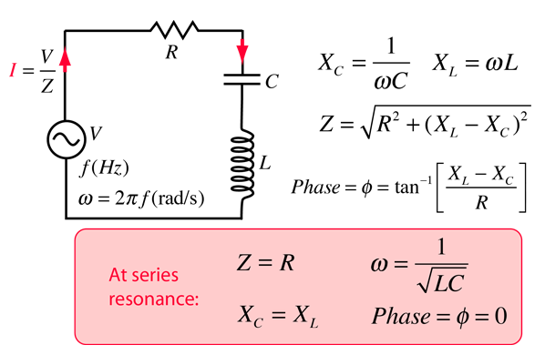
The RLC series circuit is a very important example of a resonant circuit. It has a minimum of impedance Z=R at the resonant frequency, and the phase angle is equal to zero at resonance.

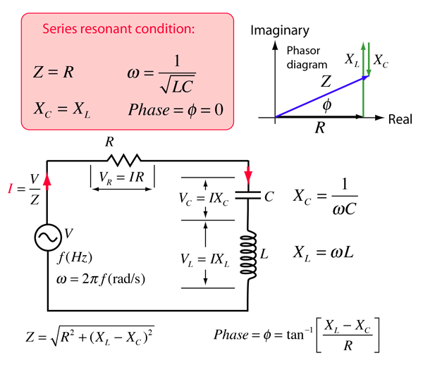
One way to visualize the behavior of the RLC series circuit is with the phasor diagram shown in the illustration above. The phasor diagram shown is at a frequency where the inductive reactance is greater than that of the capacitive reactance. This would occur at a frequency above the resonant frequency.

Calculation
Index

Capacitance concepts

Inductance concepts

AC circuit concepts
 
HyperPhysics***** Electricity and Magnetism R Nave
Go Back


RLC Series Impedance

The frequency dependent impedance of an RLC series circuit:
For C = x10^ F = μF = pF
and L = x10^ H = mH = microHenries
at angular frequency ω = x10^ rad/s,
frequency = x10^ Hz = kHz = MHz
and resistance R = x10^ ohms = kohms = Megohms,

the impedance is

Z = x10^ ohms = kohms = Megohms

at phase φ = degrees.
The resonant condition is
Angular frequency ω = x10^ rad/s,
Frequency f = x10^ Hz
Z = R = x10^ ohms
Phase φ = 0
Default values will be entered for unspecified parameters, but all component values can be changed. Click outside the box after entering data to initiate the calculation. Note that for cases where the resistance is very small, the resonant frequency of a parallel resonant circuit is approximately the same.
AC behavior of RLC series circuit
Add calculation of voltages and current
Index

Capacitance concepts

Inductance concepts

AC circuit concepts

Inductance concepts

AC circuit concepts


Resonant Frequency Calculator
 
HyperPhysics***** Electricity and Magnetism R Nave
Go Back