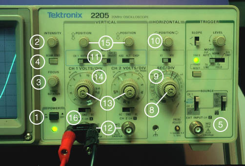
Oscilloscope Controls
-
On/Off. Do not use the wall plug as an on/off switch. Good switches help to control electrical transients which can be harmful to sensitive circuit components.
- Intensity. Adjust the brightness of the trace until you can just see all the details of the waveform. If the trace is too bright you will not get the best data, your eyes will get very tired, and you could damage the scope.
- Focus. Rotate this button until the trace is sharp.
- Beam finder. If you do not find a trace, push this button. The screen will display what quadrant the trace is in. You can then use the horizontal (#10) and vertical controls (#15) to move the trace to the middle of the screen.
- Triggering source and mode. You will use the scope to observe signals that repeat frequently. The scope must start the sweep at the same point on the waveform every time in order to produce a stable image on the screen. This function is called "triggering". For many common applications you should the source switch on "internal" and the mode switch to "auto". This lets the scope decide when to trigger.
- Trigger Slope. Usually the signal voltage will equal the triggering voltage twice, once going up and once coming down. A trigger slope control enables you to select which voltage the scope will trigger on.
- Trigger Level. This sets an internal voltage which is compared to the voltage of the input signal. When the input signal voltage equals the trigger voltage, the scope triggers. If you get an image that seems to be a superposition of many waves, turn the level knob back and forth slowly until you get a stable image.
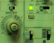
- Sweep calibration. This enables you to change the horizontal scale. Unless this knob is turned all the way clockwise, the scope is not calibrated and your data will be worthless. Turn this knob clockwise until it clicks and check it frequently as you take data.
- Sweep. This determines the horizontal scale for the oscillograph. The scale is read in the upper white window. Its units are seconds/division. See Timebase illustration
- Horizontal position. This enables you to move the signal back and forth along the X-axis. This determines, in effect, the value the signal will have at the origin.
- Channel select. Most oscilloscopes are dual trace. This means that they can display two signals at once, which is why there are two signal ports and two sensitivity controls.
- Signal ports. There is one signal port for each channel. It is a BNC connector for this oscilloscope.
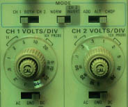
- Sensitivity calibration. This knob is used to change the vertical scale. If it is not turned all the way clockwise, the scope will be uncalibrated and your data will be worthless. Check this knob frequently as you take data.
- Sensitivity. This determines the vertical scale. It is read in the left hand white window. The units are volts/division. See Voltage Sensitivity illustration
- Vertical position. This knob controls the vertical position of the trace. You will find it very convenient when you are setting or reading voltages.
- AC/DC select. When this is set to "AC" the DC part of the signal is filtered out by a capacitor placed in series between the signal input and the scope. When the selector is set to "ground", the beam will move to zero volts. When the selector is set to "DC", the entire signal will be displayed on the scope.
|
Index
Electronics concepts |